Model reference
ZX5-400 Thyristor Rectifier Arc Welder Repair Reference
A WelderData reference for ZX5-400 style thyristor rectifier DC arc welders, focusing on SCR output control, current adjustment, trigger evidence and older DC power-source fault routing.
Database summary
ZX5-400 style welders are traditional DC arc welding power sources using transformer power conversion and thyristor-controlled rectification. Compared with a simple silicon rectifier machine, the thyristor stage adds a control layer: welding current is adjusted by the SCR firing angle and the feedback/command circuit that controls it.
This means a ZX5-400 no-output or current-adjustment fault should not be treated like an inverter PWM fault. The repair path should first separate input and transformer evidence, then SCR module condition, gate trigger evidence, current command, feedback and output cable condition.
Functional power path
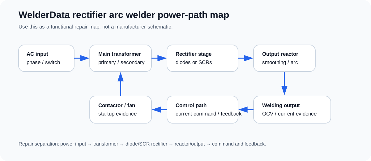
Thyristor rectifier sections
| Section | What it controls | Repair evidence to collect |
|---|---|---|
| Main transformer | Supplies the SCR rectifier bridge. | Primary energization, secondary AC balance, contactor state and overheating evidence. |
| SCR / thyristor rectifier | Converts AC to adjustable DC by phase control. | Anode-cathode short, gate-cathode condition, heat-sink mounting and module symmetry. |
| Trigger circuit | Sends gate pulses at the required firing angle. | Trigger transformer/output, missing gate pulse, unequal phase trigger and control supply. |
| Current command | Sets the desired welding current. | Panel potentiometer, remote/current command line and command voltage behavior. |
| Feedback / protection | Regulates output and blocks unsafe operation. | Current feedback, thermal state, overload behavior and abnormal shutdown evidence. |
Typical ZX5-400 repair routing
| Symptom | First separation | Likely section |
|---|---|---|
| Fan / contactor works but no welding output | Confirm transformer secondary AC and SCR output DC. | SCR stage, trigger circuit or output cable path. |
| Current cannot be adjusted | Check current-setting control, trigger firing change and feedback response. | Command potentiometer, trigger board, SCR phase-control circuit or feedback. |
| Output is too low | Check phase/input, transformer secondary, SCR firing and output reactor/cable. | Phase loss, weak trigger, open SCR path or output wiring loss. |
| Output unstable | Compare trigger evidence across phases and inspect SCR heat/symmetry. | Unequal trigger, bad SCR module, feedback noise or poor output connection. |