Inverter power-stage diagnostics
Inverter Welder Topology Identification and Repair Risk
Identify the inverter topology and power path before powering up, replacing devices or assuming one branch represents the whole machine.
Database summary
Topology identification helps prevent unsafe power-up and repeated device failure. A single-ended, half-bridge, full-bridge, soft-switching or resonant inverter does not fail or restart in exactly the same way.
Before replacing IGBTs, MOSFETs or driver parts, identify the power path, branch count, driver symmetry, snubber or resonant parts and output rectifier arrangement.
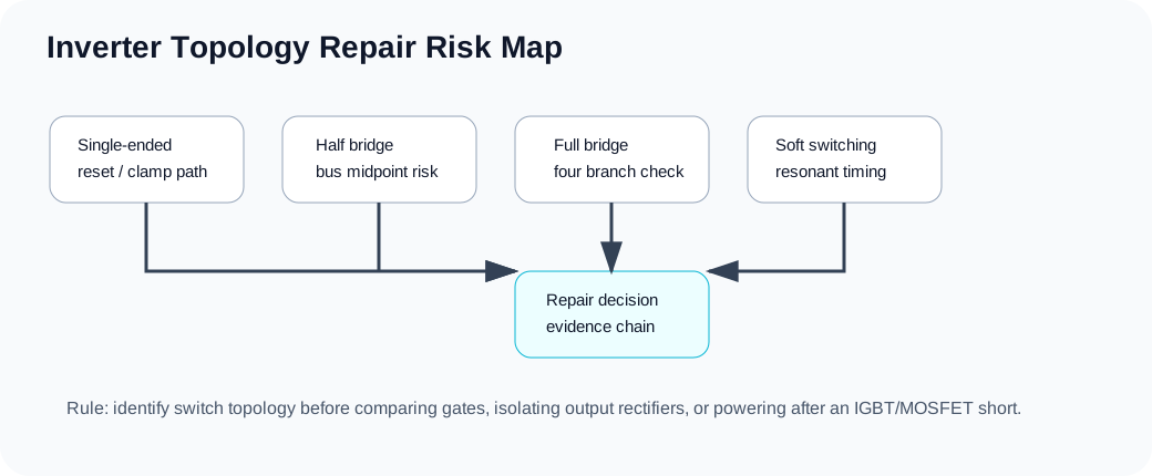
What to identify first
| Evidence | Why it matters | Repair risk |
|---|---|---|
| Number and layout of power switches | Separates single-ended, half-bridge, full-bridge and multi-device modules. | Wrong branch assumption can hide a failed companion device. |
| Gate-drive isolation and branch symmetry | Shows whether each switch pair receives the same timing and bias. | Asymmetric gate drive can destroy new devices immediately. |
| Snubber / resonant / soft-switching parts | Defines commutation stress and restart risk after a short. | Replacing only IGBTs can leave the original failure cause active. |
| Output rectifier and reactor path | Shows whether the inverter can deliver real loaded current. | OCV may be present while the arc remains weak. |
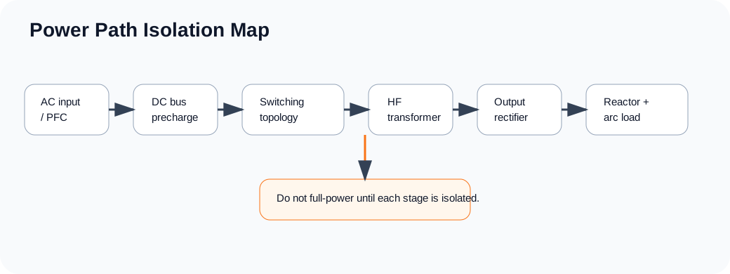
Diagnostic path
| Symptom | Repeated IGBT failure, lamp limiter bright, unknown inverter board, weak loaded output or unsafe restart after short. |
|---|---|
| Evidence | Topology, branch layout, driver symmetry, snubber/resonant parts, output rectifier and reactor path. |
| Circuit section | Input rectifier, DC bus, inverter bridge, gate-drive transformer/driver, output rectifier and feedback. |
| Next pages | IGBT/MOSFET keeps blowing · Soft-switching main loop · PWM feedback diagnosis |