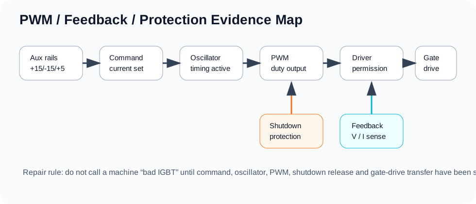
Inverter Welder PWM, Protection and Gate-Drive Diagnostic Workflow
Trace the command from the controller to every IGBT without applying full DC-bus energy until every branch has been proven safe.
What this workflow must prove
Locate the exact boundary where the command disappears: controller, protection, buffer, driver transformer or isolated module, gate branch, or power stage. PWM at one controller pin is not proof that an IGBT receives a safe gate waveform.
Reference-ground rule
ControllerUse the UC3846 or SG3525 ground pin.
Driver primaryUse the buffer/transformer-primary return.
Isolated driverUse that channel's isolated supply return.
Final gateUse the emitter/source of the device being measured.
A scope ground clip on the wrong return can short isolation, destroy parts or create a misleading waveform.
PWM-to-gate measurement order
Discharge the DC bus and clear power-stage/output shorts.
Power only the control and driver sections.
Confirm controller VCC and VREF.
Confirm the RT/CT oscillator or sync waveform.
Check shutdown, current-sense, soft-start and feedback conditions.
Compare controller output A and B at the IC pins.
Check buffer stages and the driver transformer primary or isolated-driver inputs.
Verify every isolated driver supply and return.
Compare each transformer secondary or driver output with the power devices disconnected.
Measure gate-emitter at each device reference under reduced energy.
Compare polarity, rise/fall behavior and dead time between branches.
Proceed through staged power-up while monitoring current and protection.
Decision branches
VREF missing
Check VCC, external reference loading and the controller before following the driver chain.
Oscillator missing
Check RT/CT, sync loading and controller condition.
Shutdown active
Separate a valid protection event from leakage, a damaged comparator path or false current-sense signal.
Output A/B unequal
Disconnect external loading to distinguish the controller from the buffer/driver input.
Primary pulse present, isolated output missing
Check the transformer winding, isolated supply, clamp parts or driver module.
Gate pulses look correct, protection trips under load
Check actual output current, current-sense polarity/filtering and the power/output stage.
Controller and protection checkpoints
UC3846 provides current-mode control, pulse-by-pulse current limiting, undervoltage lockout, soft-start, shutdown and dual outputs. SG3525 provides oscillator, soft-start, shutdown and alternating outputs. Confirm the actual IC and package before applying any pin number.
Driver transformer or isolated driver module
Compare equivalent channels. A correct input does not prove a correct output: confirm isolated supply, return, fault output and gate-drive output for an M57962AL or discrete isolated driver.
Trace the signal boundary instead of replacing the controller, driver and IGBTs together.
Gate-emitter branch comparison
Compare polarity, amplitude, rise, fall and dead time at the emitter/source reference of each device. Do not impose a universal gate-voltage value: the driver supply, clamp network and device family determine the correct waveform.
Staged power-up
Control supply only.
Driver outputs with power devices disconnected.
Gate network connected under reduced energy.
Current-limited DC-bus test with no welding load.
Short controlled load test while monitoring current, protection and temperature.
Stop conditions
Any bus, output or semiconductor short remains.
The reference ground for a live measurement is uncertain.
Shutdown/current-sense remains active without explanation.
Reviewed M57962AL reference set — used for driver supply, input, fault-output and isolation checks; confirm the exact module suffix before using a pin map.
WelderData ZX7-250 field notes — used for measurement order and branch comparison; raw courseware and board-specific values are not published as universal specifications.
Related repair map
Follow the evidence path from symptom to measurement, circuit and repair case.