Repair workflow
MZ1-1000 Pre-Weld Setup Checklist: Travel, Wire Feed and Initial Wire Position
WelderData setup workflow for MZ1-1000 submerged arc welders: K2 debug mode, W2 travel speed, AN3 / AN4 wire jog, initial wire position and welding-mode return.
Database summary
This workflow records the practical setup sequence for an MZ1-1000 automatic submerged arc welder before welding is started. It is intended for technicians checking travel movement, wire-feed jog behavior and initial wire position after control-board or motor-control service.
The key diagnostic idea is to separate control power, carriage movement and wire-feed positioning before the weld sequence is enabled. If these checks are skipped, a later arc-start fault may be blamed on the arc-voltage feedback loop even though the carriage or wire-feed preparation was never confirmed.
WelderData setup map
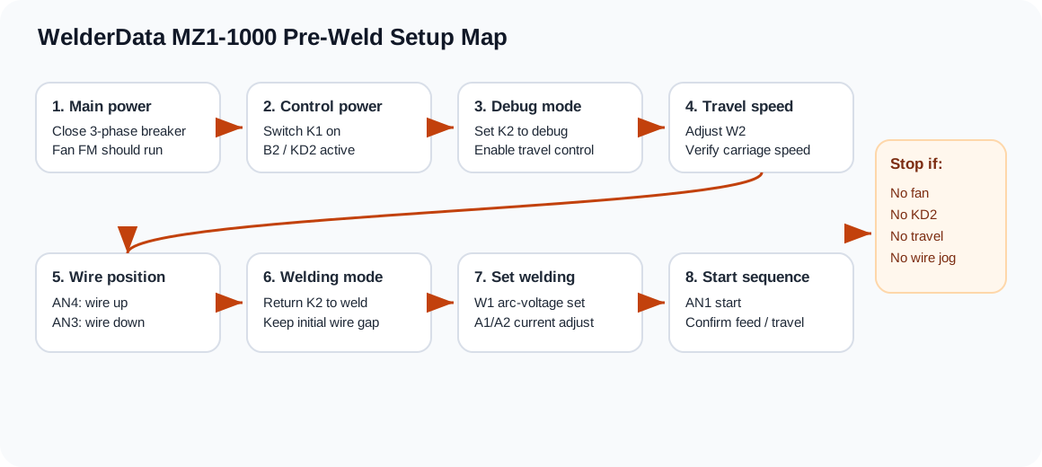
Pre-weld setup sequence
- Close the three-phase air breaker and confirm the fan motor FM operates. If the fan does not run, do not continue into travel or wire-feed diagnosis.
- Switch on K1 and confirm the control transformer path and power indicator behavior. The control system should be awake before motor-control checks are interpreted.
- Set K2 to the debug / adjustment position. This enables travel testing without treating the machine as already in the welding sequence.
- Adjust W2 and verify the travel carriage speed. The technician should confirm smooth speed response, stable carriage motion and correct direction behavior before returning K2 to welding mode.
- Use AN4 and AN3 to jog the wire-feed motor up and down. These jog buttons are for initial wire-position adjustment before the weld start command.
- Set the electrode wire to the required initial position relative to the workpiece and flux bed. Poor starting position can imitate arc-start faults.
- Return K2 to the welding position only after travel and wire-feed jog behavior are confirmed.
- Proceed to the welding start sequence and observe whether the machine enters down-feed, contact, retract and feedback-controlled wire feed in the expected order.
What each setup check proves
| Check | What it proves | If abnormal |
|---|---|---|
| Fan FM runs after breaker close | Main supply and basic machine power are present. | Stop and check incoming power, fan supply and power switching. |
| K1 / KD2 control response | Control transformer and basic low-voltage control path are active. | Check control transformer, fuses, indicator path and control wiring. |
| K2 debug mode and W2 response | Travel carriage speed-control path can be adjusted before welding. | Check W2, KP2 trigger path, M2 motor circuit and direction switch S7. |
| AN3 / AN4 wire jog | Wire-feed motor can be manually positioned before start. | Check M1 motor circuit, J4 path, jog-button wiring and wire-feed supply. |
| K2 returned to welding mode | The machine is ready for the automatic weld sequence. | Leaving K2 in debug mode can prevent normal start logic. |
Related pages
MZC controller settings that affect first start
| Setting | Repair use | Evidence to record |
|---|---|---|
| Welding current / voltage setpoint | Confirms whether the controller is requesting a realistic weld condition. | Record set value before changing power-source boards. |
| Crater current / crater voltage | Used when stop-end wire sticking or crater-fill behavior is abnormal. | Compare start behavior and stop behavior separately. |
| Travel speed | Incorrect speed can be mistaken for unstable current or poor power-source regulation. | Confirm W2 or controller speed command in debug mode. |
| Arc-start mode | Retract start and scratch/contact start do not fail in the same way. | Record selected start mode before diagnosing wire-feed reversal. |
| Wire-feed mode | Constant-speed and variable-speed feed must match the source characteristic. | Check mode when current hunts or wire feed does not stabilize. |
| Extended-cable setting | Long control cable selection changes field behavior and compensation. | Use extended mode when cable length is beyond the standard setup. |