Preventive maintenance cornerstone
Printable Welding Machine Preventive Maintenance Checklist
A cross-brand inspection record that turns maintenance findings into fault routes and preserves evidence for the next service interval.
Printable maintenance asset
Use a schedule, not a generic “clean the welder” note
Preventive maintenance should detect changes before they become board failures: loose high-current connections, blocked airflow, metal dust tracking, worn torch/feeder parts, damaged cables, unstable gas/air systems and early thermal evidence. The interval must be shortened for grinding dust, high duty cycle, mobile work, humidity and vibration.
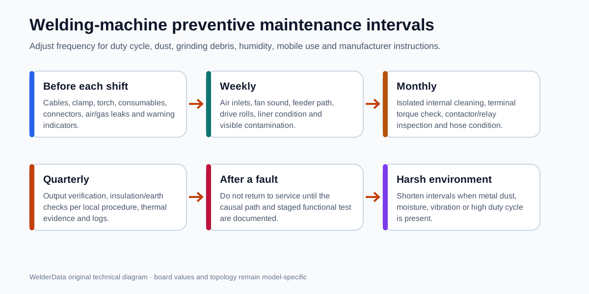
Maintenance frequency by use condition
| Condition | Adjustment | Reason |
|---|---|---|
| Clean indoor bench, light duty | Use the base schedule and manufacturer interval. | Lower contamination and thermal cycling. |
| Grinding/cutting in the same area | Inspect air paths and internal cleanliness more frequently. | Conductive metal dust can bridge high-voltage nodes. |
| High duty cycle or hot climate | Shorten fan, heatsink, terminal and temperature checks. | Thermal stress accelerates connection and component failure. |
| Mobile/site use | Inspect cables, connectors, enclosure and internal fasteners after transport. | Vibration and impact loosen or crack connections. |
| Humid or corrosive environment | Increase insulation, contamination and connector inspections. | Moisture and corrosion create leakage and intermittent faults. |
| Plasma/MIG with air, gas or feeder systems | Add consumable, hose, pressure, liner and drive-roll checks. | Process-system faults often imitate electronic faults. |
Welding Machine Preventive Maintenance Record
Before each shift
Weekly
Monthly or more often in dust
Quarterly / planned service
Release decision
What internal inspection should and should not do
Internal cleaning is not permission to direct high-pressure air at every component. Follow the manufacturer method. Isolate mains power, discharge the bus, protect bearings and delicate controls, and prevent conductive debris from being driven deeper into connectors or windings. Never use moisture or a conductive cleaning agent on an energized or insufficiently dried board.
Inspect before cleaning so the contamination pattern is not erased. Dust concentrated around a hot resistor, relay, driver transformer or fan intake can reveal the causal path. Photograph carbon tracking, loose terminals, cracked solder and overheated connectors before repair.
Maintenance findings that should open a diagnostic workflow
| Finding | Open next |
|---|---|
| Fan weak, intermittent or stopped | Cooling/fan supply and thermal-protection workflow. |
| Contactor/relay chatters | Auxiliary power and control-rail stability workflow. |
| Output lug or work clamp overheated | High-resistance connection and output-current path. |
| Repeated torch consumable damage | Gas/air, pilot arc, current and process settings. |
| Metal dust around driver/control board | Insulation, leakage, gate-drive and shutdown evidence. |
| Fault appears only when hot | Thermal switch, fan, mounting, solder and component drift. |
Related WelderData maintenance and test records
Manufacturer schedule remains primary
Use the exact owner's/service manual for safety precautions, disassembly, cleaning method, torque values and maintenance intervals. Miller's official manuals and parts portal, for example, directs users to unit-specific safety, operation, maintenance, troubleshooting and parts information by model or serial number. This WelderData checklist is a cross-brand evidence record, not a replacement for the machine manual.
Last technical review: July 13, 2026.
Related repair map
Continue with the next piece of evidence, not another generic article.