Diagnostic workflow
ZD5 / MZC Submerged Arc Welder Fault Flowcharts
A WelderData routing page for ZD5 welding power sources and MZC submerged arc tractors: power indicator faults, fan-running/no-weld states, output stops during welding, unstable current and wire-sticking problems.
Database summary
This workflow treats the submerged arc system as three linked sections: the ZD5-style welding power source, the MZC tractor/controller and the welding process setup. A symptom such as “fan runs but no welding output” should not immediately be treated as a bad SCR module. First confirm the supply, indicator circuit, contactor action, output evidence, thermal state, controller command and wire-feed behavior.
The most useful repair idea from this dataset is symptom routing. Start with the visible state, then use a small number of measurements to separate power-source faults from tractor/controller faults and process-setting faults.
WelderData fault-routing map
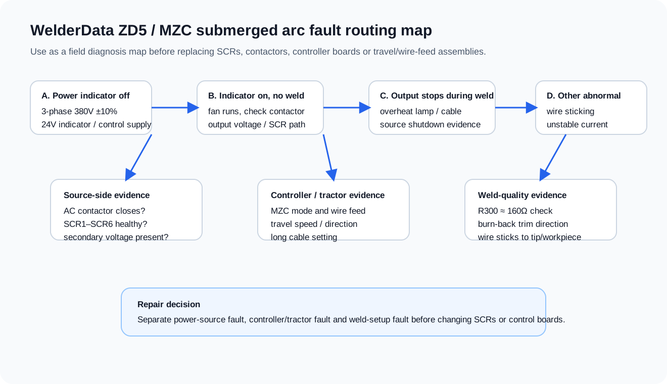
Functional map for routing ZD5 / MZC power, controller, SCR, contactor, thermal and weld-quality faults.
A. Power switch on, indicator off or abnormal start
| Check | Expected evidence | Repair interpretation |
|---|---|---|
| Three-phase input | Supply should be within the correct 380V-class range and not phase-lost. | If missing or far outside range, do not diagnose the control board yet. |
| Power indicator circuit | Indicator supply path should be present. A 24V-class indicator/control path is a useful first split. | Indicator off with correct mains suggests control supply, indicator wiring, fuse or transformer-side checks. |
| Input protection and fuses | Fuse state and fuse damage pattern should be recorded. | A normally opened fuse and a vaporized fuse do not imply the same fault energy. |
B. Indicator on, fan runs, but welding cannot start
This is the most common misrouting point. Fan operation proves only part of the control supply path. Continue toward enable and output evidence.
| Evidence | Likely section | Next check |
|---|---|---|
| AC contactor does not close | Start command, interlock, contactor coil or controller output | Confirm start button, controller output and contactor coil supply. |
| Contactor closes but no output voltage | Power-source rectifier / transformer / SCR trigger section | Check main transformer secondary evidence and SCR1–SCR6 status. |
| Output voltage exists but no stable welding | Controller interface, wire-feed control or process feedback | Check tractor mode, wire feed, output cable and feedback path. |
| Manual feed works but weld sequence does not | Controller mode, start sequence or interface between tractor and source | Return to MZC controller setup and source-enable evidence. |
C. Output stops suddenly during welding
- Check whether the thermal protection indicator or over-temperature state is present before changing semiconductors.
- Inspect output cable continuity, connector tightness and work return. A broken or loose welding cable can mimic power-source failure.
- Record whether the stop is repeatable after the same welding time, same current or same travel condition.
- If the power section stops but controller functions remain alive, separate thermal/protection shutdown from contactor-release and SCR-trigger loss.
D. Welding current unstable or wire sticks
| Symptom | Check first | Adjustment / interpretation |
|---|---|---|
| Welding current unstable | Wire diameter, source characteristic, constant-speed/variable-speed feed mode and output cable | Do not replace SCR devices before matching process mode and checking cabling. |
| Current unstable with source-side suspicion | SCR1–SCR6, transformer secondary evidence and feedback resistor path | R300 around 160Ω is a useful reference point in this routing pattern. |
| Wire sticks to contact tip | Arc voltage, burn-back timing and stop sequence | Lower weld voltage or adjust burn-back direction according to the observed sticking mode. |
| Wire sticks to workpiece | Arc voltage too low, stop sequence or crater condition | Raise weld voltage or correct crater/burn-back timing. |
| Wire sticks at the end of weld | Burn-back potentiometer and crater-fill setting | Use the stop-sequence evidence, not only the weld-start behavior. |
Maintenance checks that prevent false faults
| Maintenance point | Typical interval | Why it matters |
|---|---|---|
| Tractor connector and cable connections | Before each work period | Loose connections can look like control-board or feeder faults. |
| Flux nozzle and contact tip | Before each work period | Wear or blockage changes arc stability and wire sticking behavior. |
| Power-source cable terminals | Before each work period | Heating, voltage drop and unstable current often begin at cable joints. |
| Contactor contacts | Periodic inspection | Burned contacts can cause intermittent source enable and output loss. |
| Internal cleaning | Periodic inspection | Dust and flux contamination increase insulation and cooling risk. |
| Relay contacts in the controller | Longer-term inspection | Intermittent relay contacts can break start, feed or stop sequencing. |
Related WelderData pages
Use with MZ / MU / MZD model-family routing
ZD5 / MZC fault flowcharts are most useful after the repair path has been placed into the correct model-family context. If the machine is a different MZ, MU, MZD or MZN variant, first identify whether the symptom belongs to power-source enable, tractor motion, wire feed or arc-voltage feedback.