Repair Routing
Traditional vs Inverter Welder Repair Routing
Use this routing page to separate old transformer, generator and rectifier welders from inverter and process-control welders before choosing measurements or replacement parts.
Database summary
This WelderData workflow compares major welding-machine architectures so a technician does not apply an inverter-style repair path to a transformer welder, or replace a control board when the real fault is a brush, tap switch, contactor, work clamp, electrode-pressure path or SCR trigger circuit.
The page is intended as a routing layer. Use it before choosing a specific model page when the machine family is known but the fault path is still unclear.
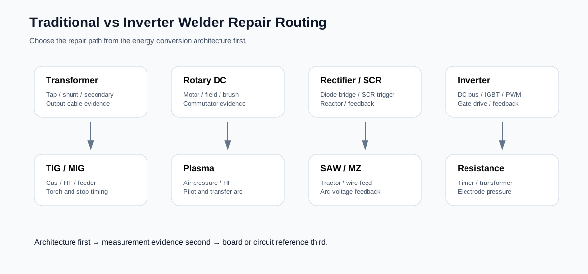
Architecture-first routing table
| Machine family | Main energy path | Common first checks | Do not misdiagnose as | Detailed workflow |
|---|---|---|---|---|
| AC transformer arc welder | Mains transformer, tap switch, movable core / shunt, secondary output and welding leads. | Input supply, tap contact, movable core travel, secondary continuity, holder and work clamp. | Control board or IGBT failure; many units have no inverter board. | AC transformer fault routing |
| Rotary DC arc welder | Drive motor, DC generator, field winding, brush / commutator and output reactor. | Motor run state, field excitation, current rheostat, brush contact, commutator, generator output. | Static rectifier or PWM control failure. | Rotary DC fault routing |
| Silicon rectifier arc welder | Main transformer, diode rectifier bridge, reactor and DC output leads. | Transformer secondary, rectifier diode mode, output reactor, cable and clamp resistance. | SCR trigger fault when the design uses fixed diode rectification. | Rectifier fault routing |
| Thyristor / SCR rectifier welder | Main transformer, SCR rectifier, trigger board, current command and feedback. | Sync signal, gate trigger, current command, feedback and SCR health. | Output diode failure only; missing trigger can mimic a bad power module. | Rectifier output control |
| IGBT / MOSFET inverter welder | Input rectifier, DC bus, inverter switch stage, HF transformer, secondary rectifier and feedback. | DC bus, auxiliary rails, PWM, gate drive, IGBT / MOSFET, output fast diodes and staged restart. | Simple output-cable fault; repeated IGBT failure often has driver or snubber root cause. | IGBT / MOSFET keeps blowing |
| MIG / MAG / CO2 welder | Power source plus torch switch, gas valve, wire-feeder motor, voltage command and stop sequence. | Torch command, gas, wire feed, remote / local control, burn-back, output voltage and work return. | Power-source fault only; feeder and control-cable faults are common. | MIG / MAG fault routing |
| TIG / AC-DC TIG welder | Output power source plus torch switch, gas timing, HF or touch-start, AC polarity or pulse control. | Gas, torch switch, HF, spark gap, start mode, auxiliary rails, current feedback and output mode. | Main output failure only; HF and gas timing faults may be separate circuits. | TIG model-series routing |
| Plasma cutter | Power source plus air pressure, HF / pilot arc, torch consumables and arc-transfer path. | Air pressure switch, solenoid, HF transformer, spark gap, nozzle / electrode, work clamp and transfer arc. | Control board failure when the real issue is air pressure or torch consumables. | KLG-60 plasma routing |
| MZ / submerged arc welder | Power source, tractor controller, wire-feed motor, travel carriage, arc-voltage feedback and source interface. | Tractor run state, wire feed, source enable, arc-voltage feedback, contact tip, work return and stop sequence. | Power-source fault only; tractor and feedback faults can mimic source failure. | SAW model-variant fault index |
| Resistance welding machine | Transformer secondary current, timer / schedule, electrode pressure, secondary circuit and cooling. | Timer command, transformer current, electrode force, electrode face, secondary path, cooling water and contact resistance. | Arc-welder output fault; resistance welders fail through pressure/timing/current interaction. | Resistance welding routing |
Repair routing rule
Do not use the same first test for every welding machine. A ZX7 inverter with a charged DC bus needs bus discharge, IGBT and gate-drive checks. A rotary DC welder needs brush, commutator and field checks. A resistance spot welder needs transformer current, timer and electrode pressure checks. A plasma cutter may fail because the air-pressure permission path is open even when the power source is healthy.
When to move from architecture to board-level references
| Move deeper when | Next layer | Example |
|---|---|---|
| Input and output cables are confirmed but output is missing. | Power-stage circuit reference. | Rectifier bridge, SCR trigger, IGBT inverter, HF start or resistance transformer path. |
| Power path is present but command does not change output. | Control / feedback reference. | SG3525, UC3846, CA3140 feedback, shunt / CT / Hall signal, SCR phase control. |
| Protection trips repeatedly after parts are replaced. | Protection and staged-restart workflow. | IGBT driver protection, DESAT / overcurrent, thermal, undervoltage and snubber checks. |
| Process behavior fails while the source appears alive. | Process-control workflow. | TIG HF, MIG feeder, plasma air/HF, SAW tractor, resistance welder pressure/timer. |
Related WelderData routing pages
Topology recognition before power-stage repair
Before replacing IGBTs, driver modules or control boards, identify whether the welder is single-ended, half-bridge, full-bridge or soft-switching. The number of gate branches, bus-balancing risk, transformer reset path and output rectifier stress change the safe diagnostic route.
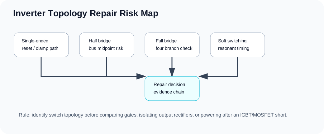
Topology recognition before power-stage repair
Before replacing IGBTs, driver modules or control boards, identify whether the welder is single-ended, half-bridge, full-bridge or soft-switching. The number of gate branches, bus-balancing risk, transformer reset path and output rectifier stress change the safe diagnostic route.