Diagnostic workflow
ZX7-250 Complete H7B Repair Sequence
A WelderData case-sequence hub connecting the ZX7-250 lamp-limiter short indication, H7B / IGBT short isolation, driver-output branch checks, 3846 primary-drive checks, current feedback and final staged power-up validation.
Database summary
This WelderData record is a navigation and reasoning hub for the full ZX7-250 repair pattern. It is useful when a machine begins with a hard input-short symptom, a lamp limiter stays bright, the power device path is suspect and the technician needs a controlled path from fault isolation to final output validation.
The sequence does not treat the failed H7B, IGBT or MOSFET as an isolated part. It links the DC bus, output rectifier path, gate-drive transformer, four secondary drive branches, 3846 driver-primary section, 102 capacitor, 22Ω resistor path, auxiliary rails, pulse indication, CT feedback, shunt measurement and final low-load test into one repair logic.
WelderData complete sequence map
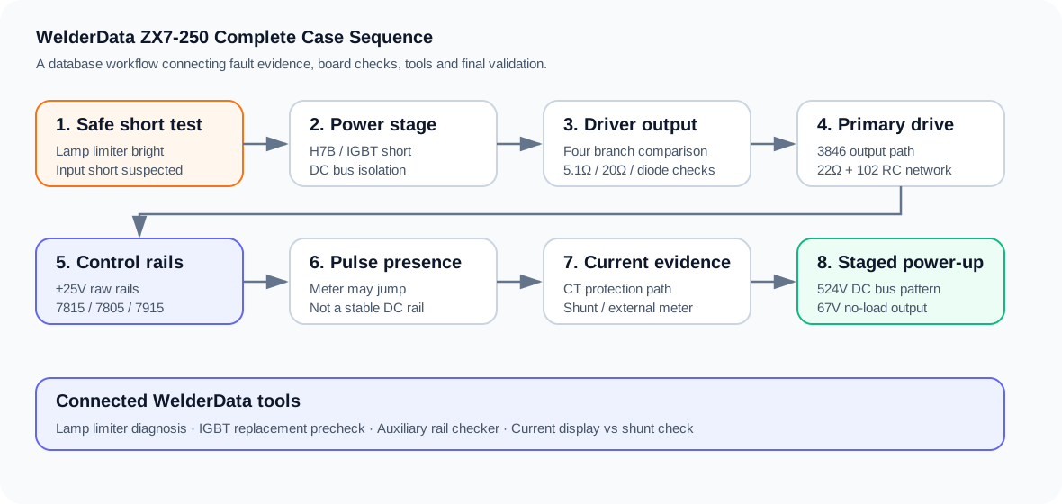
Step-by-step sequence
| Stage | Main evidence | WelderData action |
|---|---|---|
| 1. Lamp-limiter short screen | Series bulb stays bright or indicates a hard load on the input path. | Do not move to full mains testing. Use the lamp-limiter tool and isolate bridge, DC bus, power-device and auxiliary paths. |
| 2. H7B / power-device isolation | A shorted H7B, IGBT or MOSFET can place the 500V-class bus under direct stress. | Remove the suspect device path from the circuit and confirm the short is not still present through the output rectifier or bus path. |
| 3. Output rectifier and bus checks | Secondary fast diodes, output choke and bus components can mimic or repeat the same failure. | Check diode-mode behavior, DC bus condition, relay/boost path and output stage before installing new devices. |
| 4. Four gate-drive branch comparison | One branch may differ from the other three after a power-device failure. | Compare each isolated output branch. Pay special attention to gate resistors, small fast diodes, clamp paths and asymmetric readings. |
| 5. 3846 primary driver network | The failure may start before the transformer secondary side. | Check the 3846-style output path, primary-side driver device, 102 capacitor, 22Ω resistor and transformer primary network. |
| 6. Auxiliary rails and pulse indication | Control-board activity does not prove the driver is ready for power devices. | Confirm ±25V raw rails, +15V, -15V, +5V and check for pulse / jumping indication at the transformer primary path. |
| 7. Current evidence | Panel current response is not the same as real welding current. | Use CT protection logic for fault interpretation and use an external shunt or current meter for actual output verification. |
| 8. Staged power-up | The repaired machine must prove control response, bus energy, no-load output and light-load current in order. | Reassemble, apply fresh thermal compound, start conservatively, measure the bus, verify no-load output and then test real current. |
Measurement checkpoints
- Lamp limiter: bright and sustained behavior is treated as a stop condition, not a normal power-up result.
- DC bus: a repaired ZX7-250 pattern may show a 500V-class bus after the relay/boost path is restored; one recorded validation pattern measured about 524V DC.
- Control rails: ±25V raw rails, +15V, -15V and +5V should be checked before blaming PWM output.
- Gate drive: the transformer primary is a pulse path. A multimeter may show jumping or unstable indication instead of a clean DC value.
- Real output: no-load output around 67V and external current evidence during a light-load test are stronger than display-only confirmation.
Minimum measurement table for this workflow
Use this sequence as a measurement record, not only as a reading path. The important evidence is the relationship between the lamp-limiter result, the DC bus short state, the driver branch symmetry and the final output validation.
| Stage | What to record | Healthy / usable evidence | Stop or recheck condition |
|---|---|---|---|
| Series lamp start | Bulb behavior after capacitor charge | Brief flash then dimming, or controlled behavior after the shorted section is isolated | Bright lamp that stays bright; do not bypass the limiter |
| DC bus isolation | Bridge, capacitor bank, power device and output rectifier resistance / diode-mode checks after discharge | No hard short remaining across the high-voltage bus after the failed branch is removed | Low-ohm short remains with the power devices removed |
| Gate-drive evidence | Four output branch comparison, gate resistor / fast diode / clamp path, primary driver network | Branches are broadly symmetrical and no branch shows a shorted small part | One branch differs strongly from the other three, or the 102 / 22Ω primary network is suspect |
| Control power and pulse check | +15V, -15V, +5V rails and pulse / jumping indication at the driver-primary path | Stable rails and a pulse indication suitable for a low-risk restart | Missing rails, locked protection input or no pulse indication |
| Final validation | DC bus, no-load output voltage and external current meter / shunt evidence | Bus and no-load output are consistent with the machine class and a light-load current test is controlled | Panel display changes but real current or no-load output is not verified |
Evidence quality ladder
WelderData treats a burned device as the beginning of the repair, not the end of it. A stronger repair record climbs from visual evidence to isolated measurement and then to controlled output validation.
| Evidence level | Example | How to use it |
|---|---|---|
| Weak | Visible H7B / IGBT damage, carbon mark, cracked resistor | Good for locating a suspect area, but not enough to install new power devices |
| Medium | Diode-mode or resistance abnormality in one power branch | Supports component removal and branch isolation |
| Strong | Four-branch comparison, rail confirmation, pulse indication and lamp-limiter retest | Supports staged power-up, still not full-load operation |
| Final | DC bus measurement, no-load output, external current meter or shunt validation | Supports closing the repair case as a recovered output path |
Stop conditions before moving to the next step
- The lamp limiter stays bright after the visible failed power device has been removed.
- The DC bus still reads as a hard short after the rectifier, bus capacitor and output rectifier paths are separated.
- A gate-drive branch is not symmetrical with the other branches and the small resistor / fast diode path has not been repaired.
- The 3846-style primary driver network has no pulse indication or has suspect 102 capacitor / 22Ω discharge behavior.
- Control rails are missing, unstable or pulled down by a board fault.
- The machine has not been validated with no-load output and real-current evidence.
Related case pages and tools
Repair-use note
This workflow is intentionally conservative. A technician may find a visibly failed power device early in the process, but replacing it before checking the drive branch, primary driver network, auxiliary rails and staged restart evidence can reproduce the failure. WelderData treats the visible failed device as one symptom inside a full inverter repair chain.
Related repair map
Follow the evidence path from symptom to measurement, circuit and repair case.