Model reference
IGBT-ZX7-400 Inverter Welder Repair Reference
A WelderData repair reference for IGBT-ZX7-400 style inverter stick welders, focusing on the main power path, IGBT failure checks, control-board evidence, protection behavior and staged restart after power-device repair.
Database summary
IGBT-ZX7-400 machines are a common class of inverter stick welders built around rectified mains, a high-voltage DC bus, IGBT inverter switching, a high-frequency transformer, secondary fast rectification, output filtering and a current-feedback control loop. The exact board layout varies by manufacturer, but the repair path should stay evidence-first: identify the symptom, isolate the power section, check the driver and feedback paths, then restart through controlled stages.
This page is a repair database entry, not a welding technique guide. Use it when a machine powers on but has no output, repeatedly fails IGBTs, shows protection behavior, has weak arc output or has been repaired but cannot be trusted for full-power restart.
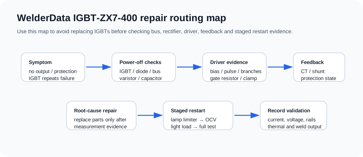
WelderData repair routing map
Functional block structure
| Section | What it does | Repair evidence to collect |
|---|---|---|
| AC input and rectifier | Converts mains input to high-voltage DC bus. | Input wiring, breaker/fuse state, bridge rectifier, NTC/soft-start parts and DC bus presence. |
| DC bus capacitors | Store energy for the inverter bridge and absorb ripple. | Bulging, leakage, ESR suspicion, charge/discharge behavior and bus short checks. |
| IGBT inverter | Switches the DC bus into the high-frequency transformer. | C-E short, G-E short/leakage, gate resistor damage, snubber or clamp abnormalities. |
| Gate-drive section | Provides isolated or transformer-coupled gate pulses. | Drive bias, pulse symmetry, branch comparison, damping parts and turn-off path. |
| Secondary rectifier | Rectifies transformer output into welding DC. | Fast diode module short/open, diode-mode asymmetry and output inductor / shunt evidence. |
| Control and feedback | Regulates current and blocks PWM during faults. | Current command, feedback signal, protection input, thermal switch and PWM enable state. |
Power-device replacement precheck
Do not treat an open cabinet and visibly damaged IGBT as the full diagnosis. Repeated IGBT failure usually points to a hidden companion fault.
| Before installing IGBTs | Normal evidence | Stop condition |
|---|---|---|
| Input rectifier and DC bus | No hard short across bus; rectifier diode paths are not shorted. | Lamp limiter stays bright or bus measures as hard short. |
| IGBT gate-emitter | No hard short; gate resistor and clamp parts intact. | Gate-to-emitter short, burnt resistor or missing discharge path. |
| Driver branches | All corresponding branches look similar by resistance and diode checks. | One branch clearly differs from the others. |
| Secondary rectifier | No shorted output diode module. | Output diode-mode check suggests a shorted rectifier that will load the inverter. |
| Auxiliary rails | Driver/control rails present and stable before full-bus testing. | Weak rails, missing negative drive, no PWM enable or active protection state. |
Common IGBT-ZX7-400 symptoms
| Symptom | First separation | Next WelderData route |
|---|---|---|
| Input trips or lamp limiter stays bright | Separate bridge rectifier, DC bus capacitor, IGBT and secondary rectifier shorts. | Lamp limiter short diagnosis |
| IGBT fails again after replacement | Check driver symmetry, gate resistor/clamp, snubber/resonant parts and output rectifier loading. | IGBT / MOSFET keeps blowing |
| Fan/display works but no output | Separate auxiliary rails, PWM enable, protection input, current feedback and driver output. | Powers on but no output |
| Protection lamp or shutdown | Check thermal switch, current feedback, output short and driver lockout before replacing the board. | ZX7 series common fault table |
| Weak or unstable arc | Separate current command, shunt/CT feedback, output diode, output inductor and panel control. | Current display vs shunt check |
Deep repair table: component checks before restart
Use this table when the machine has already shown power-stage damage or when a previous IGBT replacement failed. The goal is to separate a failed component from the condition that destroyed it.
| Check item | Repair interpretation | Stop condition |
|---|---|---|
| IGBT visual and offline check | Record package cracking, burn marks, G-E short, C-E hard short or abnormal diode behavior before removing other evidence. | Any C-E hard short or G-E short means the machine must stay out of full-power testing until the driver and load side are checked. |
| Gate resistor and discharge path | Open or burned gate resistors, missing discharge resistors, clamp diode damage or unequal branch readings can destroy a replacement device. | One branch differs clearly from the others, or the gate path cannot discharge after testing. |
| Varistor / surge protection | Input surge parts and overvoltage clamps should not be cracked, carbonized or shorted. A failed varistor can point to surge stress rather than a normal device aging fault. | Shorted or exploded surge part, repeated breaker trip or line-side damage before the rectifier is cleared. |
| Snubber / resonant / damping parts | Check capacitors, damping resistors and resonant parts around the bridge. These parts may look secondary but can decide turn-off spike and commutation stress. | Burned resistor, cracked capacitor, asymmetric readings or soft-switching condition not credible. |
| Secondary fast rectifier | A shorted output rectifier can overload the transformer and force the primary bridge into destructive current. | Diode-mode check suggests shorted output diode or both output terminals look hard-shorted after discharge. |
| Cooling and mechanical mounting | Heatsink pressure, insulation sheet, thermal compound, fan airflow and thermal switch wiring are part of the electrical repair. | Loose module, contaminated heatsink, fan fault or thermal switch circuit open/uncertain. |
IGBT-ZX7-400 repair sequence checklist
- Record the original symptom. Note whether the machine tripped input power, stayed bright on a lamp limiter, powered on with no output, entered protection, or failed during welding.
- Discharge and perform power-off checks. Check the DC bus, bridge rectifier, IGBT C-E / G-E paths, secondary fast rectifier and obvious burned parts before applying power.
- Separate the failed device from the cause. A bad IGBT is not a root cause until gate-drive, snubber, feedback, output rectifier and cooling evidence agree.
- Compare symmetrical branches. On multi-device bridges, compare like-for-like gate resistors, fast diodes, clamp parts and transformer / driver branch paths.
- Confirm control power and driver permission. Do not install devices into a board with missing +15V / -15V / +5V, active protection or unknown PWM-enable state.
- Use staged restart. Start with current-limited or isolated validation where possible, then record DC bus, open-circuit output and a light-load welding result before full-current testing.
Common damaged areas in IGBT-ZX7 repair
| Damaged area | Typical symptom | Repair note |
|---|---|---|
| Input rectifier / DC bus | Breaker trips, lamp limiter bright, bus short. | Do not fit a new IGBT until the rectifier and bus capacitors no longer look shorted. |
| IGBT module / switch pair | C-E short, module crack, immediate input trip. | Check companion driver branch and snubber before treating it as a single-part replacement. |
| Gate-drive branch | New device fails, uneven output, no reliable switching. | Compare branches; a single bad resistor or diode can make one device switch differently. |
| Fast output rectifier | No output, weak arc, power-stage overload, repeated device stress. | Use diode-mode checks and compare module legs rather than judging by appearance. |
| Feedback / current command | Current cannot regulate, weak arc or protection after short welding. | Separate panel command, shunt/CT feedback and protection state before replacing the main board. |
| Protection / thermal path | Works briefly, then shuts down or fails under load. | Fan, thermal switch, heatsink pressure and duty-cycle evidence should be recorded. |
Maintenance and restart notes
- Clean conductive dust before high-voltage testing; carbonized dust can create misleading leakage paths.
- Inspect fan airflow, heatsink contact and thermal switch wiring before judging the control board.
- Use a lamp limiter or other controlled restart method after power-stage repair.
- Validate open-circuit voltage and light-load welding before full-current testing.
- Record the replaced parts together with the evidence that justified replacement.