Inputs unequal
Fault is upstream in the controller or buffer.
Board · power-device driver
Document inputs, returns, supplies and outputs before measuring. Channel-to-channel comparison is safer than applying a generic pinout.
A welder driver board may use a pulse transformer, discrete push-pull stages, optocouplers or hybrid driver modules. Identify PWM input, driver supplies, isolation boundary, gate outputs and fault signals before assigning connector pins.
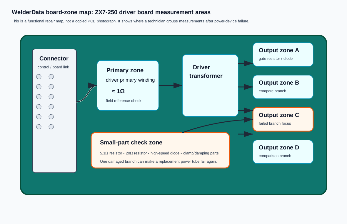
| Group | Possible signals | First evidence |
|---|---|---|
| Control input | PWM A/B, enable, shutdown | Compare both channels at the primary return. |
| Driver supply | Shared or isolated rail per channel | Measure unloaded and loaded stability. |
| Gate output | Gate, emitter/source return, clamp | Label pairs before disconnecting. |
| Fault/protection | FO, desaturation or overcurrent feedback | Confirm polarity and normal inactive state. |
Power only the driver section. Verify inputs, isolated supplies, fault output and unloaded gate outputs. Use the matching return for each isolated channel.
Fault is upstream in the controller or buffer.
Driver device, isolated supply, transformer winding or clamp fault.
Gate resistor, power device, connector or emitter return fault.
Separate a real protection event from supply loss or a damaged detection path.
Follow the evidence path from symptom to measurement, circuit and repair case.